WELCOME

WELCOME TO ZEESHAN SIDDIQUI BLOG:

How to create a blog

Sunday, 1 April 2012

MINESTO TIDAL KITE


Marine energy comes from two main sources:

waves, which originate from wind; and

tides, which are caused by the gravitational

pull of the moon and sun. One of the benefits of

harnessing tidal currents is that, unlike wind and waves,

they are predictable and offer an ecologically friendly

and reliable source of energy.

Minesto has developed a new kind of tidal energy

solution based on its Deep Green concept, which uses

low water speeds to create energy. This revolutionary

concept makes it possible to install and operate plants

in areas where no other known technology can operate

cost effectively, thus expanding the number of sites

where tidal energy can be generated.

A groundbrea king and unique solution

The Deep Green technology converts energy from

tidal stream flows into electricity by way of a novel

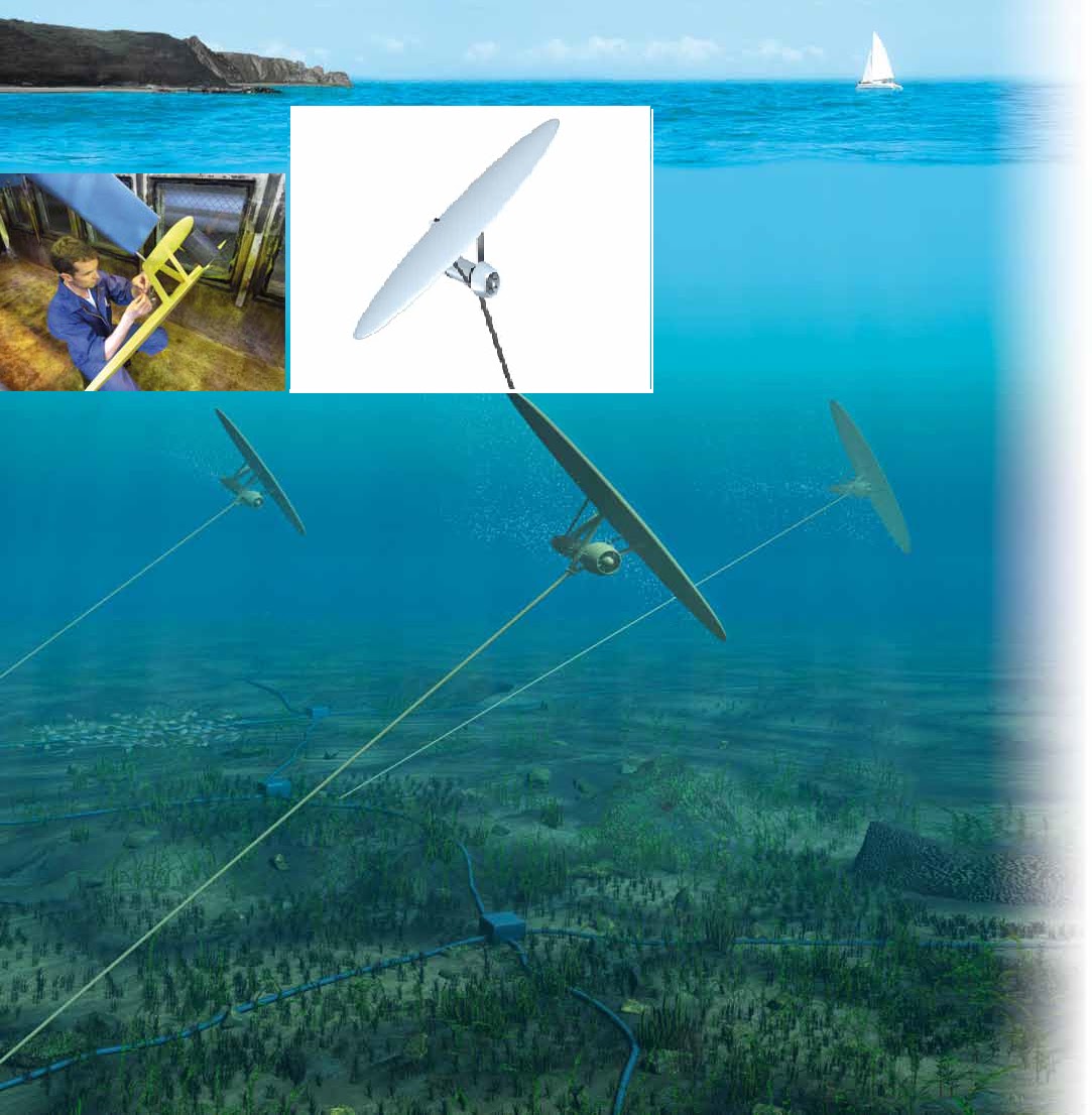
principle: an underwater kite. The kite consists of

a wing, turbine and generator, and is attached by

a tether to a fixed point on the ocean bed. The speed

of the kite determines the flow velocity to the turbine.

Electricity is transmitted onshore through a power

cable inside the tether.

 “What makes our technology unique is that we can


 extract energy, in a cost-efficient way, from low stream


 velocity,” said Arne Quappen, Development Manager,


 Minesto. “Our competitors use tidal streams that


 are habitually 2.5 meters/second (8.2 feet/second),


 whereas we can use tidal streams between 1.5 and
 2 meters/second." Another advantage of our system,
compared to our competition, is that their installations are bigger,
 heavier and more difficult to install.
” he said.
The technology developed by Minesto is lightweight and

small compared to other tidal solutions, resulting in

 reduced costs in material, transport, installation, service,

maintenance and dis assembly."

“We have to compete with other more established

energy sources such as coal or nuclear,” Quappen

said. “The fact that we are not as established as

traditional energy producers is a tough challenge and

one that we have to meet by improving the reliability and

cost- effectiveness of our solutions.”

Designing energy-producing underwater

kites with CATIA PLM Express

Minesto uses CATIA to design innovative tidal energy solutions. The flexibility

and rapidity with which it can create its designs enables Minesto to show potential

customers design variations based on their requirements. Compared to its previous

CAD system, model size is no longer a problem, allowing Minesto to work on

complex models and assemblies of its products.

Arne Quappen
Development Manager, Minesto

With CATIA, we can work on more complex

models and assemblies with all the related

details. Model size is no longer a problem.

Catering to the nee ds of potential

customers

Minesto is currently developing and testing prototypes

of its solution before going to production. “Our objective

 is to create a robust design of our kite that we can then

adapt to the needs of our customers,
                                   

” Quappen said.

“As a development company we are in discussion with

potential customers to collect their requirements and to

implement them in our commercial products.”

In 2010, Minesto chose CATIA PLM Express from

Dassault Systèmes for its 3D design work and for

drawing production. “Our previous solution lacked

the design precision and flexibility we needed,”

Quappen said. “During this initial product development

phase, it is important for us to create

different design variations quickly and to

show them to potential customers before

converging on the right design. With

CATIA, as opposed to our previous

solution, we can work on more complex

models and assemblies with all the

related details. Model size is no longer a

problem.”

Semcon, a Dassault Systèmes’ partner,
 helped Minesto implement CATIA
provided training and consulting services.
 “Semcon’s industry know-how and
extensive knowledge of CATIA accelerated
our learning curve

,” Quappen said.

Minesto, based in Gothenburg, Sweden, is a

spin-off of the Saab Group. Formed in 2007,

the company develops technology for a new

type of tidal power plant. After validating

the cost-effectiveness and viability of its

designs, Minesto was chosen by the Carbon

Trust to participate in its Marine Energy

Accelerator program. Minesto was recently

granted £350,000 from the Carbon Trust to

deploy the first prototype of its Deep Green

underwater kite. Carbon Trust´s programs

support those companies that are most

promising in the development of alternative

energy solutions.

Minesto

                                   By Dora Laîné]

                                   For more information:

                                   www.minesto.com

Sunday, 4 March 2012

12v to 220v inverter 180 watt


Wednesday, 29 February 2012

Transformerless 12V DC Power Supply

Electric Shock Hazard. In the UK,the neutral wire is connected to earth at the power station. If you touch the "Live" wire, then depending on how well earthed you are, you form a conductive path between Live and Neutral. DO NOT TOUCH the output of this power supply. Whilst the output of this circuit sits innocently at 12V with respect to (wrt) the other terminal, it is also 12V above earth potential. Should a component fail then either terminal will become a potential shock hazard.

Below is a project by Ron J, please heed the caution above and Ron's design notes.


MAINS ELECTRICITY IS VERY DANGEROUS.
transformerless power supply


If you are not experienced in dealing with it, then leave this project alone.Although Mains equipment can itself consume a lot of current, the circuits we build to control it, usually only require a few milliamps. Yet the low voltage power supply is frequently the largest part of the construction and a sizeable portion of the cost.
This circuit will supply up to about 20ma at 12 volts. It uses capacitive reactance instead of resistance; and it doesn't generate very much heat.The circuit draws about 30ma AC. Always use a fuse and/or a fusible resistor to be on the safe side. The values given are only a guide. There should be more than enough power available for timers, light operated switches, temperature controllers etc, provided that you use an optical isolator as your circuit's output device. (E.g. MOC 3010/3020) If a relay is unavoidable, use one with a mains voltage coil and switch the coil using the optical isolator.C1 should be of the 'suppressor type'; made to be connected directly across the incoming Mains Supply. They are generally covered with the logos of several different Safety Standards Authorities. If you need more current, use a larger value capacitor; or put two in parallel; but be careful of what you are doing to the Watts. The low voltage 'AC' is supplied by ZD1 and ZD2.
The bridge rectifier can be any of the small 'Round', 'In-line', or 'DIL' types; or you could use four separate diodes. If you want to, you can replace R2 and ZD3 with a 78 Series regulator. The full sized ones will work; but if space is tight, there are some small 100ma versions available in TO 92 type cases. They look like a BC 547. It is also worth noting that many small circuits will work with an unregulated supply. You can, of course, alter any or all of the Zenner diodes in order to produce a different output voltage. As for the mains voltage, the suggestion regarding the 110v version is just that, a suggestion. I haven't built it, so be prepared to experiment a little.

I get a lot of emails asking if this power supply can be modified to provide currents of anything up to 50 amps. It cannot. The circuit was designed to provide a cheap compact power supply for Cmos logic circuits that require only a few milliamps. The logic circuits were then used to control mains equipment (fans, lights, heaters etc.) through an optically isolated triac. If more than 20mA is required it is possible to increase C1 to 0.68uF or 1uF and thus obtain a current of up to about 40mA. But 'suppressor type' capacitors are relatively big and more expensive than regular capacitors; and increasing the current means that higher wattage resistors and zener diodes are required. If you try to produce more than about 40mA the circuit will no longer be cheap and compact, and it simply makes more sense to use a transformer

Transformerless 5V DC Power Supply


Transformerless 5V DC Power Supply
This board takes AC mains input from 100V to
250V AC and output regulated +5V DC providing
current up to 50mA. Great for running small
and almost zero heat generation.
In most non-battery applications, the power to the
microcontroller is normally supplied using a wall
mounted transformer, which is then rectified,
filtered and regulated. In most applications, this
method of generating the regulated voltage is
cost effective and can be justified. However,
there are applications where the main controller
and low voltage is not required by other
components except the microcontroller in
application. In these instances, the cost of the
transformer becomes the sizable cost factor in
the system. For example, most fire alarms &
round the clock monitoring alarms are powered
this way.
Transformerless power supplies, thus, have a distinct advantage in cost as well as in size. The
disadvantages of using a transformerless power supply are low current supply and no isolation from
the AC line voltage.
The microcontrollers usually draw a maximum of 20 mA, even at the highest frequency and voltage
of operation, therefore low current availability is not an issue. The main disadvantage of
transformerless supplies is that they don't offer isolation from the HV line.
One down side of this circuit that it is not isolated from mains so it should not be used in
applications requiring touch of any contact from user. If any part even though +5V side is touched it
would cause shock to the user. Please be careful about touching when using it during experiments
or final applications.


Warning! An electrocution hazard exists during experimentation with transformerless circuits that
interface to AC mains wall power. There is no transformer for power-line isolation in the circuit, so
the user must be very careful and assess the risks from line-transients in the user’s application.
An isolation transformer should be used when probing the circuit during experimentation.

Monday, 30 January 2012

WATER-LEVEL CONTROLLER


WATER-LEVEL CONTROLLER:
K.P. VISWANATHAN
Here is a simple, automatic waterlevel
controller for overhead tanks
that switches on/off the pump motor
when water in the tank goes below/
above the minimum/maximum level. The
water level is sensed by two floats to operate
the switches for controlling the pump
motor.
Each sensors float is suspended from
above using an aluminium rod. This arrangement
is encased in a PVC pipe and
fixed vertically on the inside wall of the
water tank. Such sensors are more reliable
than induction-type sensors. Sensor
1 senses the minimum water level, while
sensor 2 senses the maximum water level
(see the figure).
Leaf switches S1 and S2 (used in tape
recorders) are fixed at the top of the sensor
units such that when the floats are
lifted, the attached 5mm dia. (approx.) aluminium
rods push the moving contacts
(P1 and P2) of leaf switches S1 and S2
from normally closed (N/C) position to
normally open (N/O) position. Similarly,
when the water level goes down, the moving
contacts revert back to their original
positions.
Normally, N/C contact of switch S1 is
connected to ground and N/C contact of
switch S2 is connected to 12V power supply.
IC 555 is wired such that when its
trigger pin 2 is grounded it gets triggered,
and when reset pin 4 is grounded it gets
reset. Threshold pin 6 and discharge pin 7
are not used in the circuit.
When water in the tank goes below
the minimum level, moving contacts (P1
and P2) of both leaf switches will be in
N/C position. That means trigger pin 2
and reset pin 4 of IC1 are connected to
ground and 12V, respectively. This triggers
IC1 and its output goes high to
energise relay RL1 through driver transistor
SL100 (T1). The pump motor is
switched on and it starts pumping water
into the overhead tank if switch S3 is ‘on.’
As the water level in the tank rises,
the float of sensor 1 goes up. This shifts
the moving contact of switch S1 to N/O
position and trigger pin 2 of IC1 gets connected
to 12V. This doesn’t have any impact
on IC1 and its output remains high
to keep the pump motor running.
As the water level rises further to reach
the maximum level, the float of sensor 2
pushes the moving contact of switch S2
to N/O position and it gets connected to
ground. Now IC1 is reset and its output
goes low to switch the pump off.
As water is consumed, its level in the
overhead tank goes down. Accordingly,
the float of sensor 2 also goes down. This
causes the moving contact of switch S2 to
shift back to NC position and reset pin 4
of IC1 is again connected to 12V. But IC1
doesn’t get triggered because its trigger
pin 2 is still clamped to 12V by switch S1.
So the pump remains switched off.
When water level further goes down
to reach the minimum level, the moving
contact of switch S1 shifts back to N/C
position to connect trigger pin 2 of IC1 to
ground. This triggers IC1 and the pump is
switched on.
The float sensor units can be assembled
at home. Both the units are identical, except
that their length is different. The depth
of the water tank from top to the outlet
water pipe can be taken as the length of the
minimum-level sensing unit. The depth of
the water tank from top to the level you
want the tank to be filled up to is taken as
the length of the maximum-level sensing
unit. The leaf switches are fixed at the top
of the tank as shown in the figure.
Each pipe is closed at both the ends by
using two caps. A 5mm dia. hole is drilled
at the centre of the top cap so that the
aluminium rod can pass through it easily to
select the contact of leaf switches. Similarly,
a hole is to be drilled at the bottom
cap of the pipe so that water can enter the
pipe to lift the float.
When water reaches the maximum
level, the floats should not go up more
than the required distance for pushing
the moving contact of the leaf switch to
N/O position. Otherwise, the pressure on
the float may break the leaf switch itself.
The length of the aluminium rod is to be
selected accordingly. It should be affixed
on the metal/thermocole float using some
glue (such as Araldite).